
Thermal Error Characteristic of Ballscrew Feed System
- Lo Jm
- Oct 23, 2023
- 3 min read
Agreeing to ISO230-2 and ISO230-3 testing model, a few tests have been attempted on xaxis of nourish framework of DM4600 vertical processing machine by making utilize of testing instrument such as Heidenhain VM182 straight grinding, Pt100 warm resistance module and Fluke infrared thermometer. Through testing, changing rules of pivotal warm blunder, backhaul blunder and outspread warm blunder beneath certain turn rate has been gotten as well as the relationship between temperature increase and warm blunder changing beneath shifting working condition.
With the expanding of speed and speeding up of machine apparatus, the impact of working exactnessfrom warm flow characteristics gets to be increasingly self-evident. Progressing warmflow characteristics has gotten to be one of pressing issues to create machine apparatus of tall execution. Bolster framework is an vital portion of machine instrument, whose situating blunder specifically influences working precision of the machine apparatus. There are basically 6 sorts of situating mistakes of the nourish framework agreeing to sources: 1. blunder of control framework; 2. fabricating mistake (geometrical blunder) of each component; 3. mistake coming about from pretightening constrain of lead screw and bearing; 4 warm blunder caused by temperature variety; 5. mistake of misplaced force (drive solidness and torsional unbending nature) caused by hub heading and torsional stack;6. kinematic mistake caused by increasing speed and deceleration. Among these blunders, warm misshapening mistake caused by temperature is the foremost genuine, which is additionally troublesome to controll. Appropriately, it is critical to ponder the run the show between temperature rise and warm misshapening of bolster framework to progress working exactness of the machine apparatus.
The machine tool applied in the article is DM4600 vertical milling machine. VM182 linear grating (as shown on the right side of Figure 1) produced by German company is used to measure the thermal errors at different positions on the x- axis of feed system. Pt100 thermal resistance is applied to measure the temperature of each measured point. According to the choosing method of thermal sensitive points, the temperature sensor should be positioned closest to the thermal source. Therefore, in the experiment, temperature sensors are mainly set at this position such as actuating motor, left bearing seat, right bearing seat and guideway seat etc, while another sensor is set to measure environmental temperature. As guide screw nut generates heat by friction, contact measurement method is not available. Thus, Fluke infrared thermometer is used to measure the temperature of the midpoint in the distance of ball screw. The signal of temperature sensor is sent by PCI1716L DA&C cards to computer to process. Measured points and sensor numbers are shown in Table 1. The testing system is shown in Figure 2.
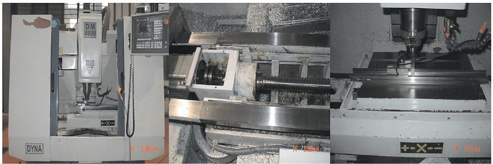
Figure 1. DM4600 vertical milling machine, x-axis of feed system and Heidenhain linear grating

Figure 2. Schematic diagram of testing system

According to ISO230-2, a criterion of measuring positioning accuracy, and ISO230-3, a criterion of evaluating thermal effect , the first step is to measure positioning accuracy Eposition in order to measure thermal error of x-axis in feed system (stroke is 0~450mm as shown in Figure 3) under certain operating condition,. To measure the positioning accuracy, work bench is ordered to move in reciprocation at a low speed˄<1m / min˅within designated distance. Get position deviation EXi of each measuring point in the designated distance by linear grating. Owing to the low velocity there is no significant thermal error to take into account, so EXi=Eposition. When thermal error being measured with operating condition constant, choosesix measuring points started with zero position within the designated distance, whose space is 90mm. And then have the work bench move in reciprocation at a certain speed wihtin the designated distance, measuring the position deviation EXi of the six measired points by linear gratging.,. Thereinto:
EXi=Eposition - Ethermalerror (1) So, EXi minus Eposition can obtain Thermal error of certain measuring point.

Figure 3. Sketch map of feed system x-axis Figure 4. Testing cycle
Comentarios